4 years in Tech and I was finally graduating. I wanted to make this graduation ceremony special. Illuminating the graduation cap caught my interest after seeing numerous examples on the internet, especially from Jamison Go's project. I thought it would be a natural spotlight. Not too messy, but on point.
Goals for this project is to:
learn and get familiar with using Arduino
make color changing process gradient yet not abrupt (white to gold, gold to blue, blue to white, and so on)
"hkim702" is the user ID I've been using on multiple occasions ever since I entered Georgia Tech as a freshmen. It was automatically given to me when I first made my account in Georgia Tech school website (buzzport ID). I thought it would be worth giving it some recognition. Also, I am a mechanical engineering major. Hence the "MECH. E". This plate will be laser cut out of 1/8 inch thick transparent clear acrylic plate.
Thanks Constantine Venizelos for helping out with the laser cutting!
Laser cutting was done at the Invention Studio. The LED strip that surrounded this plate has 10mm width. Polycarbonate U-channel with 10mm inner width is used to surround the led strip and at the same time, clamp down the acrylic plate and the mortar board together. This makes everything look neat and clean.
Arduino code
This was my first time using Arduino. It wasn't that bad. I actually regret not learning it earlier. PWM (Pulse Width Modulation) technique is used for controlling the power of each led (r,g,b).
All testings are done on breadboard before soldering
Arduino Pro Mini was used for its cheap cost (just $2 each) and small form factor.
Final prototype for control board
All these go into my left pocket during the graduation ceremony (Don't worry, my pocket didn't rip). Rocker switch is designed to slightly stick out of the pocket for easily switching between on/off even when the graduation gown is covering it. 3S LiPo battery that can be charged up to 12.6 volts was used as a power source. I was surprised how fragile arduino pro mini is when it failed with only 0.6V of over-volting (manufacturer states it can take max 12V). Luckily, I had another Arduino board for spare and step down 5V voltage regulator was used to power it this time.
White, Green Gold, Blue
Color changes repeatedly to form Georgia Tech's primary and secondary colors. Theoretically red and green lights should make yellow(gold) lights. For me, that wasn't so easy and the color gold turned out to be slightly greenish...
Improvements for future iteration:
correct color (greenish gold -> gold)
or try another interesting idea for decoration
And yes, I will be continuing my graduate studies starting Fall 2019 at Georgia Tech!
Starting on May 2018 up until May 2019 (3 semesters), I was part of EPIC (Exoskeleton and Prosthetic Intelligent Controls) lab, where I worked on research and development of powered hip exoskeleton. The project consisted of multiple teams working together synchronized, including mechanical, electrical, and experimental, which are guided by couple of graduate students, who are guided by the principle investigator, Dr. Aaron Young. I took the lead in mechanical development team in that aspect.
Goal of this research (quite more inclined to mechanical aspect) is to:
design & build a hip exoskeleton that ultimately reduces overall metabolic cost of the wearer
use ball screw based series elastic actuation
bring down the weight to light as possible
pretty much correct & improve all the flaws from the first exoskeleton iteration in the lab
Parts used for this build:
Actuator interface to C-frame
PLA 3d printed -> nylonX 3d printed (planned)
Actuator side covers/mechanical stoppers
PLA 3d printed -> nylonX 3d printed (planned)
Aluminum standoffs
6mm dia, M3 standoffs
Actuator main plates
Acrylic -> garolite -> carbon fiber (planned)
All aluminum structures
Aluminum 7075
Ball nut
Thomson part #5709574
Ball screw
Thomson part #5707538
On board computer
myRIO
Encoder
Orbis RLS sensor - absolute encoder
Motor
Maxon EC30 BLDC moter
Motor driver
ESCON module 50/5
Springs
Fiberglass bar
C-frame
Aluminum 6061 -> 7075 -> carbon fiber (planned)
Backpack housing
PLA 3d printed
Joint shafts
Carbon steel rod
Battery
5S 5000mah *2 (series connection)
Orthotic plates
Molded plastic + foam
Hip exo V1
CAD model of hip exo V1
Actuator of the 1st exoskeleton (side view)
Constantine looking good
First hip exoskeleton was already built by other students from previous semesters when I joined in the lab. It was also using a ball screw series elastic actuation but quite different in overall design. It's actuators were mounted horizontally which sticks out quite a lot in the back, preventing the wearer sit while on the device. Also, many tolerance issues in multiple joints were found which creates mechanical delays and inaccuracies in sensor readings. The weight of the single actuator in this design is approx 1.5 kg and the overall device with the battery is approx 7.8 kg. This is quite heavy so the next iteration had to be made much lighter.
Hip exo V2
Front & rear view of V2 exoskeleton
Trying on the exoskeleton V2
V1, V2 actuators in comparison (CAD)
Redesigning the actuator for the new hip exo was the first thing that had to be done. One of the biggest disadvantage of wearing exoskeleton is the weight. Even with the assist, increased weight by putting on the exo suit brings up the metabolic cost. Therefore, I personally focused on having the new design as light as possible. The new design has several advantages over the hip exo V1. The actuator is approximately 550 grams lighter when weighed, resulting in total of more than 1kg reduction in weight just from the new actuators from the full hip exo suit weight. The new actuator design has protective casing and is easy to manufacture. Advantage of vertical mounting method is that it minimizes the actuator's part sticking out the the human body shape so subject can move with less limitation, for example sitting on a chair.
Originally planned range of motion and belt tension adjustable motor mount
The old version doesn't have this feature but the new actuator's motor mount is designed so that the kevlar reinforced belt tension is adjustable by maximum 4mm. Also, original plan was to have subjects wearing hip exo with this actuators able to flex their hip 100 degrees forward and extend 30 degrees back. This was to allow them sufficient range not only for walking and running, but also sitting as well. Soon, limitation to this range of movement was found and this will be discussed more later in this post. Perimeter of the actuator is protected by 3D printed PLA covers and this will be improved with nylon/carbon fiber type filament prints for more impact resistances while maintaining sufficient rigidity (mechanical stoppers which take impacts are integrated into 3D printed walls).
Section view of the actuator
11 aluminum standoffs are basically holding the whole components together and at the same time, giving 3D printed covers compressional preload perpendicular to the filament direction, thus preventing the delamination of the 3D printed structures. Outer side of the 3D printed covers are the tunnels for the wires to go through, effectively organizing them.
Actuators assembly, mid progress
Spring is made by cutting fiberglass plate with water-jet. Installed on its sides are wheat stone bridge circuitry that feed backs how much torque is applied to the spring which bends proportionally. Each spring is calibrated by physically applying weights (5kg, 10kg, 15kg, etc) to generate linear equation for force applied (N) vs output voltage. This eliminates the spring's difference in bending (thickness tolerance issue due to water-jet) and allows accurate torque readings from both springs.
Left actuator assembled on the device
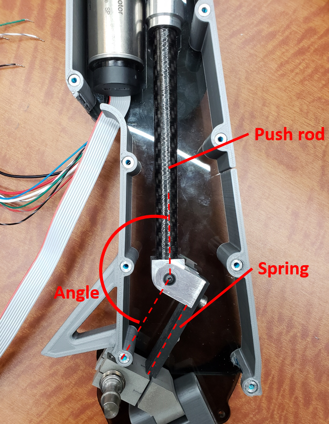
Internal view of the actuator, showing the spring
Issue with this system is when the angle between the spring and the ball screw push rod becomes too small or too great (0deg < a << 90deg and 180deg > a >> 90deg), the torque reading becomes less accurate which forced the team to limit the movement of the leg near 90 degrees between the push rod and the spring. This is why the actuators on the device is slightly leaning forward, which is to have the angle close to 90 degrees when the subject is standing straight. The change greatly hindered the original plan to allow wearer sit with the device on since the possible forward leg movement is substantially decreased.
Degree of freedoms in leg assembly
Leg interface is designed so that it supports the subject moving their leg not only forward and backward but also left and right. Circled on the top is the degree of freedom which allows the leg move forward and backward. The rotating shaft holds the magnet rig, which allows the absolute encoder to read the amount of angle moved by the subject. Other two circles allows the leg to move left and right. Joint shown in the bottom circle is added to conform easier to different body shapes of the wearer. Interface connection is clamped to the rod to allow height adjustments depending of the subject's hip length. Simple clamping method like above wasn't a perfect design in that although it holds its height, it tends to rotate. This would likely be fixed by adding key shapes or bolting holes on the rod for preventing rotation. Just like most of the metal used to make the device, leg assembly is mostly composed of 7075 aluminum for light weight and rigidity. Carbon steel are machined to become joint shafts.
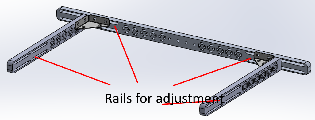
C-frame CAD model
C-frame was first neglected and only the orthotic plate interfaces were used to attach the device on to subjects. However, without the rigid frame that firmly holds the actuators, the device would flex especially when the actuators are applying assistance to the hip. This brings down the whole effectiveness of the device as torque readings become off and creates misalignment of interfaces to body. After rigid C-frame was added, most of these issues were solved but addition of aluminum bar chunks substantially increased the overall device weight. This will need to be solved in the near future with lighter materials such as carbon fiber tubes. Interesting gimmick of the C-frame is that the distance between the actuator mounts can be adjusted corresponding to subjects body size. Likewise, actuators can be pushed forward or backward.
First backpack
New backpack under development (CAD)
Backpack houses myRIO, voltage regulator, battery, pcb boards, motor driver boards, etc. All the wires coming out from the actuator (encoders on motor, motor's phase & power wires, leg angle encoder, strain gauge, etc) connects to the boards on the backpack. The backpack needs to be able to embed all those components and wires while being light and compact as possible. First version of the backpack, which is too bulky and placed far away from the center of gravity of subject is being revised and the backpack that is more compact (flatter) and has better wire management is in development.
Specification - V1 vs V2
Torque input compared to output - V1 vs V2
Device powered off compared to zero impedance mode - V1 vs V2
Above comparisons are extracted from Jeff Hsu's masters defense presentation. Total weight of the device when assembled was approximately 6.8 kg, which is 1kg lighter than the V1 exo. This weight is continuously fluctuating due to addition/subtraction or replacement of parts with improved specifications. For example, replacing metallic C-frame with lighter composite material would bring down the weight significantly. It can be noted that the V2's torque output is less than that of the V1 and that is a trade-off for achieving greater angular velocity which correlates to faster response in assistance. Mechanical superiority of V2 compared to V1 can be well noted in the plot where the commanded torque is compared to the actual output torque. V2's output torque follows the input considerably better than the V1. Also, the device is showing very high back drivability even when it is powered off, significantly closer to the supposedly zero-impedance mode where the device works to follow the leg movement of the subject with minimal resistance.
More pics - views from multiple angles
Approximately 90% of the mechanical components seen on the photo above (taken on May 2nd 2019) are designed by me :). That is including the entirety of the actuators. I'm quite satisfied to see these improvements.
Various experiments has been conducted with the device to find the optimal control strategies. Studied are biological torque control, proportional EMG control, and pattern recognition controls. Commonly used experimental devices were VICON motion capture systems, Bertec Treadmill, PARVO (for metabolic data collection), EMG (electromyography) sensors, etc.
Hip exo V3
New SEA of future device (V3)
At the same time, future exoskeleton hip exo V3 is under development as well. This has been my PURA project I worked on in conjunction to the hip exo V2. More details about this project can be found in the following video I made as a project overview: PURA video presentation. Along with the final report: PURA final report. Improvement for the future iteration could be...
use rigid composite materials to replace the metal pieces (weight reduction), especially C-frame
harmonic gear driven series elastic actuator implementation (more torque, more laterally compact)
leg bars with some kind of keys (prevent thigh interface's rotation)
"You may be wondering, why the red suit? Well, that's so bad guys can't see me bleed!"
- Dynastinai V1.5, Deadpool theme (?)
Dynastinai V1.5 is an upgrade version of my first 3lb modular combat robot, Dynastinai. Most of the parts are reused if not, modified/upgraded for better performance.
I was taking a break from Robojacket duties since I have been busy with preparing for graduating/ graduate school plans. I wasn't planning to work on improving this battlebot until the week before the competition. I saw the announcement on Facebook about the upcoming event on March 30th and thought, "Why not?".
Goals for this upgrade was to:
improve most of the flaws experienced from 2018 Motorama
fix everything and revive the robot into functioning state within 1 week
compete in Robojackets 20th Anniversary Competition
have fun
Parts I used for this build (replaced/added from old design):
Chassis extension
piece
Onyx + Kevlar
New horizontal weapon
AR500
Weapon ESC
BL heli 35A brushless
ESC
Drive motors
1000 rpm 12V DC
brushed motor
Drive motor
controllers
Scorpion Mini
12V BEC
TUZ 12V 3A step-down
regulator
Battery
3S 850mah 45C * 2 in
series
CAD model was done with Autodesk Inventor
Top view showing internal electrical components and the chassis extension piece
I decided to only use the horizontal weapon module for this competition since I haven't got a chance to fix the vertical weapon's severe vibration problem from the previous competition. I only had 1 week to complete the project, which was not enough to fix it.
Minor modifications had to be done to the chassis to fit the new DC brushed gear motors for drive, which were larger and heavier than the precious choice. It would have taken too much time to 3D print all the new chassis parts so I took it to mill and milled down sections of the chassis.
Larger capacity batteries (3S 850mah * 2 in series) compared to the last design (3S 500mah * 2 in series) were used to make sure the battery don't become fully discharged in the middle of the fight.
Invention Studio's Markforged now supports Onyx!
New horizontal weapon partially assembled
Improvements done to the electrical systems plus the chassis extension piece increased the total weight of the robot. Thus, I had to redesign the weapon to stay under the 3lb weight limit. 3/16 inch think AR 500 plate is water-jetted and then belt grounded for polished look. New weapon weighs about 290 grams, which is slightly less than 20% of the total weight of the robot.
Painting the suit in red
To make sure bad guys can't see it bleed Dynastinai has more intimidating look, I spray painted the robot with red and gave it a glossy coat. Painting & coating only added approximately 5 grams overall.
Chassis extension piece (black rectangular thing on top) and shock absorbing pads showing
During the last competition, the weapon stopped working after a huge hit exchange with the opponent. Upon examination, I was able to find out the weapon ESC wouldn't work and I figured it would be a good idea to protect the fragile electronics with shock absorbing pads. This is why I made the chassis extension piece to give more spacious room for the electrical components plus the pads. Now, all electrical components are either floating via wires inside the chassis or have protective pads surrounding them to separate them from external impacts.
12 V bec exposed
I heard successful stories in online forums about overvolting DC brushed motors and be fine with doing so. So I supplied 24 V to the 12 V rated DC brushed drive motors and practiced driving. It seemed to work fine for about 10 minutes but soon, one of the motors failed. I blame myself and no one else. I changed out the burnt motor and added a 12 V step down voltage regulator (only 3 grams!) and hooked up to the drive. The system worked flawlessly after this.
Only approx 1 gram lighter than the 1360.78 gram limit (3lb), the weight is impressively optimized
Matches:
1. Dynastinai vs. Crispi
Crispi was a drum spinner type battlebot from Robojackets.
Fight never happened and I won by opponent's forfeit.
2. Dynastinai vs. Oreo
Oreo was a wedge type bot. I decided to head on attack in on all directions to practice driving with minimal weapon spin but felt bad for over doing it. It was my first fight and since I was too eager to test the robot, I didn't notice the opponent unable to drive after several hits and kept on attacking before the opponent tapped out.
3. Dynastinai vs. Daddi
Daddi was a horizontal spinner type bot. Mid cutter. I tried to attack the opponent's sides and rear to avoid sustaining damage to my horizontal module. Also felt bad at the end. I didn't notice the opponent unable to drive after several hits and kept on attacking before they tapped out.
4. Dynastinai vs. Furi
Furi was a drum spinner type bot from Robojackets. In this fight, I wanted to test the weapon spin up to the maximum speed and see what's gonna happen.
5. Dynastinai vs. Impulse Response
Impulse Response was a horizontal spinner type bot. Under cutter. I tried to attack without giving enough time to spare in between hits since I figured the weapon spin up time for Impulse Response would be slow due to large weapon and relatively small motor. This didn't work out very well since my weapon spin up acceleration wasn't great either - another aspect to improve in the future. Also, I was quite worried since Impulse Response had greater reach in terms of weapon so I decided to attack on its sides and its rear. This turned out to be quite effective.
6. [Final] Dynastinai vs. M.A.D.
M.A.D. (Mutually Assured Destruction) was a horizontal spinner type bot. Mid cutter. I tried to attack its sides and rear to avoid getting hit. After exchanging few punches, I was unable to spin up the weapon fast. Later I noticed the heat shrink covering the weapon motor ESC and the foam pad surrounding it were partially melted. I believe the ESC got overheated and failed to function properly in the middle of the fight. This will be fixed in the future.
At the end, Dynastinai won 1st place with 6:0 win to loss ratio.
Workbench view at the end of the competition
Sustained damages
Visually, only the wheel guards and the horizontal weapon module sustained damages throughout the event. This may not seem a lot of data to analyze but I learned a lot about where to fix/improve in the next iteration of Dynastinai. Thank you members of Robojackets who worked tirelessly in organizing this event! Awesome job and hopefully they will host another competition in the future.
Improvements for future interations:
complete optimized remodeling of the chassis
botkits 22mm planetary gear DC motor for drive system
larger diameter weapon for greater reach
faster weapon spin-up time (lower KV, higher torque motor (?))


