Powered hip exoskeleton
 |
| Device as of May 2nd, 2019 |
Starting on May 2018 up until May 2019 (3 semesters), I was part of EPIC (Exoskeleton and Prosthetic Intelligent Controls) lab, where I worked on research and development of powered hip exoskeleton.
The project consisted of multiple teams working together synchronized, including mechanical, electrical, and experimental, which are guided by couple of graduate students, who are guided by the principle investigator, Dr. Aaron Young. I took the lead in mechanical development team in that aspect.
Goal of this research (quite more inclined to mechanical aspect) is to:
- design & build a hip exoskeleton that ultimately reduces overall metabolic cost of the wearer
- use ball screw based series elastic actuation
- bring down the weight to light as possible
- pretty much correct & improve all the flaws from the first exoskeleton iteration in the lab
Parts used for this build:
Actuator interface to C-frame
|
PLA 3d printed -> nylonX 3d printed (planned)
|
Actuator side covers/mechanical stoppers
|
PLA 3d printed -> nylonX 3d printed (planned)
|
Aluminum standoffs
|
6mm dia, M3 standoffs
|
Actuator main plates
|
Acrylic -> garolite -> carbon fiber (planned)
|
All aluminum structures
|
Aluminum 7075
|
Ball nut
|
Thomson part #5709574
|
Ball screw
|
Thomson part #5707538
|
On board computer
|
myRIO
|
Encoder
|
Orbis RLS sensor - absolute encoder
|
Motor
|
Maxon EC30 BLDC moter
|
Motor driver
|
ESCON module 50/5
|
Springs
|
Fiberglass bar
|
C-frame
|
Aluminum 6061 -> 7075 -> carbon fiber (planned)
|
Backpack housing
|
PLA 3d printed
|
Joint shafts
|
Carbon steel rod
|
Battery
|
5S 5000mah *2 (series connection)
|
Orthotic plates
|
Molded plastic + foam
|
Hip exo V1
 |
| CAD model of hip exo V1 |
 |
| Actuator of the 1st exoskeleton (side view) |
 |
| Constantine looking good |
First hip exoskeleton was already built by other students from previous semesters when I joined in the lab. It was also using a ball screw series elastic actuation but quite different in overall design. It's actuators were mounted horizontally which sticks out quite a lot in the back, preventing the wearer sit while on the device. Also, many tolerance issues in multiple joints were found which creates mechanical delays and inaccuracies in sensor readings.
The weight of the single actuator in this design is approx 1.5 kg and the overall device with the battery is approx 7.8 kg. This is quite heavy so the next iteration had to be made much lighter.
Hip exo V2
 |
| Front & rear view of V2 exoskeleton |
 |
| Trying on the exoskeleton V2 |
 |
| V1, V2 actuators in comparison (CAD) |
 |
| Originally planned range of motion and belt tension adjustable motor mount |
The old version doesn't have this feature but the new actuator's motor mount is designed so that the kevlar reinforced belt tension is adjustable by maximum 4mm. Also, original plan was to have subjects wearing hip exo with this actuators able to flex their hip 100 degrees forward and extend 30 degrees back. This was to allow them sufficient range not only for walking and running, but also sitting as well. Soon, limitation to this range of movement was found and this will be discussed more later in this post.
Perimeter of the actuator is protected by 3D printed PLA covers and this will be improved with nylon/carbon fiber type filament prints for more impact resistances while maintaining sufficient rigidity (mechanical stoppers which take impacts are integrated into 3D printed walls).
 |
| Section view of the actuator |
11 aluminum standoffs are basically holding the whole components together and at the same time, giving 3D printed covers compressional preload perpendicular to the filament direction, thus preventing the delamination of the 3D printed structures. Outer side of the 3D printed covers are the tunnels for the wires to go through, effectively organizing them.
 |
| Actuators assembly, mid progress |
Spring is made by cutting fiberglass plate with water-jet. Installed on its sides are wheat stone bridge circuitry that feed backs how much torque is applied to the spring which bends proportionally. Each spring is calibrated by physically applying weights (5kg, 10kg, 15kg, etc) to generate linear equation for force applied (N) vs output voltage. This eliminates the spring's difference in bending (thickness tolerance issue due to water-jet) and allows accurate torque readings from both springs.
 |
| Left actuator assembled on the device |
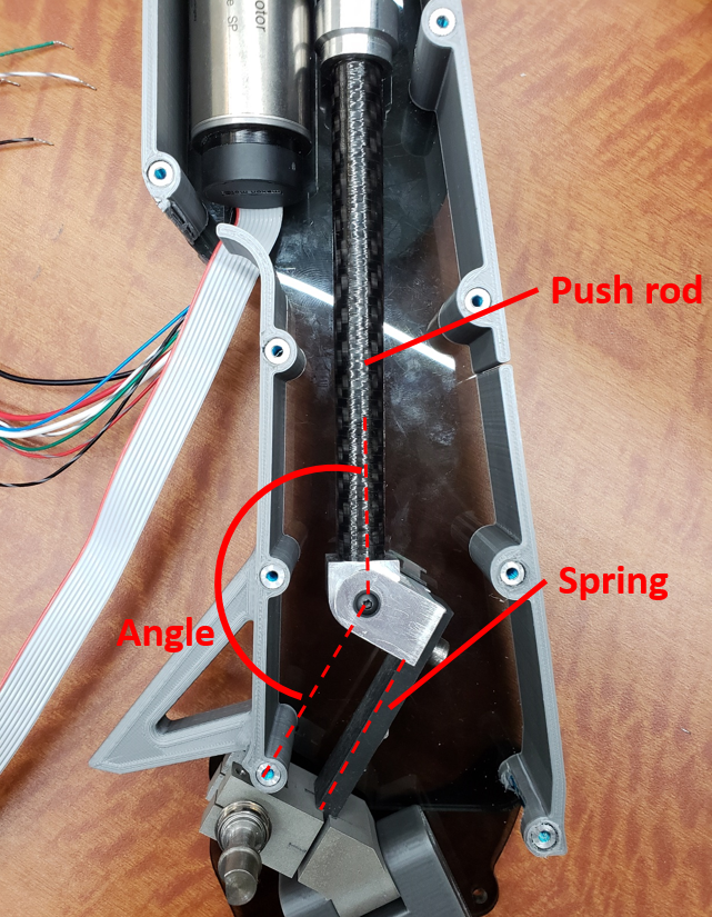 |
| Internal view of the actuator, showing the spring |
Issue with this system is when the angle between the spring and the ball screw push rod becomes too small or too great (0deg < a << 90deg and 180deg > a >> 90deg), the torque reading becomes less accurate which forced the team to limit the movement of the leg near 90 degrees between the push rod and the spring. This is why the actuators on the device is slightly leaning forward, which is to have the angle close to 90 degrees when the subject is standing straight. The change greatly hindered the original plan to allow wearer sit with the device on since the possible forward leg movement is substantially decreased.
 |
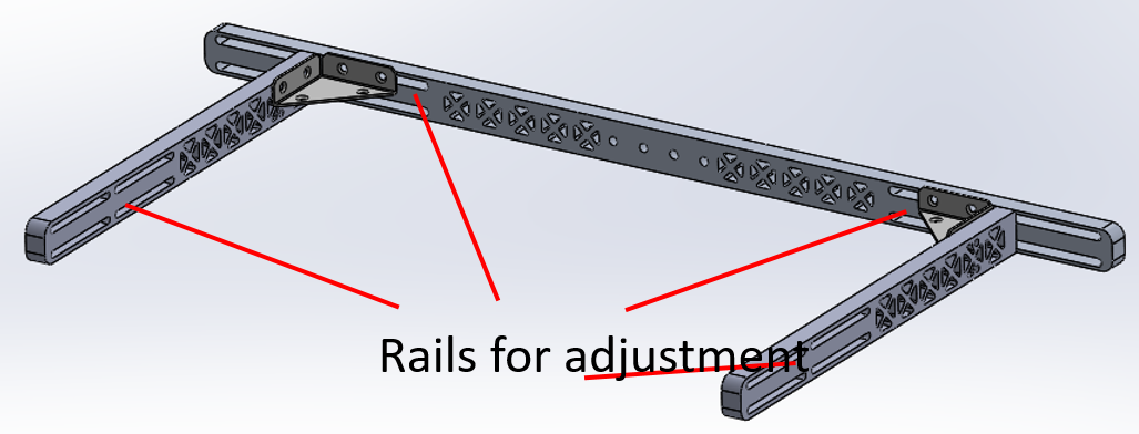
| Degree of freedoms in leg assembly |
Leg interface is designed so that it supports the subject moving their leg not only forward and backward but also left and right. Circled on the top is the degree of freedom which allows the leg move forward and backward. The rotating shaft holds the magnet rig, which allows the absolute encoder to read the amount of angle moved by the subject. Other two circles allows the leg to move left and right. Joint shown in the bottom circle is added to conform easier to different body shapes of the wearer. Interface connection is clamped to the rod to allow height adjustments depending of the subject's hip length. Simple clamping method like above wasn't a perfect design in that although it holds its height, it tends to rotate. This would likely be fixed by adding key shapes or bolting holes on the rod for preventing rotation. Just like most of the metal used to make the device, leg assembly is mostly composed of 7075 aluminum for light weight and rigidity. Carbon steel are machined to become joint shafts.
 |
| C-frame CAD model |
 |
| First backpack |
 |
| New backpack under development (CAD) |
Backpack houses myRIO, voltage regulator, battery, pcb boards, motor driver boards, etc. All the wires coming out from the actuator (encoders on motor, motor's phase & power wires, leg angle encoder, strain gauge, etc) connects to the boards on the backpack. The backpack needs to be able to embed all those components and wires while being light and compact as possible. First version of the backpack, which is too bulky and placed far away from the center of gravity of subject is being revised and the backpack that is more compact (flatter) and has better wire management is in development.
 |
| Specification - V1 vs V2 |
| Torque input compared to output - V1 vs V2 |
 |
| Device powered off compared to zero impedance mode - V1 vs V2 |
Above comparisons are extracted from Jeff Hsu's masters defense presentation. Total weight of the device when assembled was approximately 6.8 kg, which is 1kg lighter than the V1 exo. This weight is continuously fluctuating due to addition/subtraction or replacement of parts with improved specifications. For example, replacing metallic C-frame with lighter composite material would bring down the weight significantly.
It can be noted that the V2's torque output is less than that of the V1 and that is a trade-off for achieving greater angular velocity which correlates to faster response in assistance. Mechanical superiority of V2 compared to V1 can be well noted in the plot where the commanded torque is compared to the actual output torque. V2's output torque follows the input considerably better than the V1. Also, the device is showing very high back drivability even when it is powered off, significantly closer to the supposedly zero-impedance mode where the device works to follow the leg movement of the subject with minimal resistance.
 |
| More pics - views from multiple angles |
Various experiments has been conducted with the device to find the optimal control strategies. Studied are biological torque control, proportional EMG control, and pattern recognition controls.
Commonly used experimental devices were VICON motion capture systems, Bertec Treadmill, PARVO (for metabolic data collection), EMG (electromyography) sensors, etc.
Hip exo V3
 |
| New SEA of future device (V3) |
Along with the final report: PURA final report.
Improvement for the future iteration could be...
- use rigid composite materials to replace the metal pieces (weight reduction), especially C-frame
- harmonic gear driven series elastic actuator implementation (more torque, more laterally compact)
- leg bars with some kind of keys (prevent thigh interface's rotation)
- overall weight reduction
- etc, etc, etc... (there are so many)


Hello. Can I have Maxon ESCON module 50/5 CAD file? Thankyou
ReplyDeleteMy Email is Ehsan2754@yahoo.com
ReplyDelete